

ODM RCBO Factory Builds Custom Residual Current Breakers for Modern Electrical Systems
2026-08-19
Electrical safety is not a one-size-fits-all problem. When you're building or upgrading modern electrical systems, standard residual current breakers can leave dangerous gaps. An ODM RCBO factory that truly understands custom design changes that equation. At SINGI, every custom residual current breaker is engineered around your system's real-world demands—not the other way around. In this post, we'll look at how that approach prevents nuisance tripping, improves fault detection, and meets strict regional codes while keeping lead times surprisingly short.
Custom RCBOs That Start With Your Electrical Drawings, Not a Catalog
When an RCBO is chosen from a catalog, the design often bends around the device. Custom RCBOs flip that sequence. Your electrical drawings specify exactly where the protection needs to sit, what trip curves match the connected loads, and how much space is available inside the enclosure. That information becomes the starting point, not an afterthought.
Starting from drawings means every pole configuration, current rating, and residual trip level can be matched to the circuit it actually protects. There is no need to accept a close-enough catalog part or redesign a panel around a standard footprint. Manufacturers work directly from the marked-up schematics, so the finished device fits the installation without forcing compromises.
This approach also simplifies revisions. When a drawing changes, the custom RCBO changes with it, instead of sending you back to a catalog search. The result is protection that follows the engineering intent from the first line on the page to the final device in the board.
What Happens on the Factory Floor When Standard Breakers Fall Short
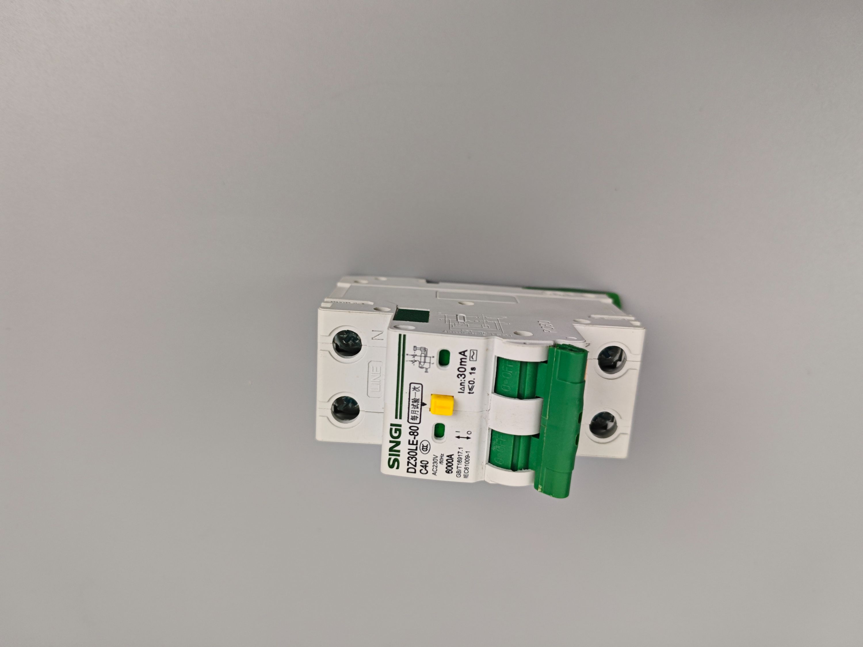
Standard breakers trip on overloads and short circuits, but real factory floors throw far messier problems at them. A motor drawing locked-rotor current for a few seconds can look identical to a dead short to a generic thermal-magnetic unit. The breaker opens, the line stops, and nobody knows whether it was a nuisance trip or a genuine fault until maintenance starts digging through cabinets. That ambiguity costs more than the minutes lost; it erodes trust in the protection scheme and pushes operators toward risky workarounds like zip-tying handles or oversizing breakers.
Harmonic-rich loads from VFDs and rectifier banks also fool standard trip curves. The breaker might hold through a distorted waveform one shift, then open on the same load the next day because ambient temperature shifted. When that happens mid-batch, the whole line can lose synchronization—conveyors jam, ovens cool unevenly, and robots fault out waiting for a signal that never arrives. Maintenance crews end up chasing ghosts while production scrap piles up.
Worst is the slow thermal damage that never trips anything. A standard breaker sized to the wire may let a slightly elevated current run for hours, heating busbars and terminals until insulation turns brittle. By the time someone smells burning plastic, the panel is already compromised. Specialty breakers with adjustable magnetic thresholds, electronic trip units, or tighter thermal memory exist precisely because standard ones ignore these slow-burn failures. On a factory floor, that gap between "protected" and "actually safe" shows up as charred lugs, unexplained downtime, and a deep reluctance to touch the electrical room during third shift.
Residual Current Protection Tuned to Modern Load Profiles
Modern loads such as LED drivers, variable frequency drives, and server power supplies generate residual currents that are far from the classic sinusoidal waveform. They often contain DC components, high-frequency harmonics, and transient spikes. A conventional AC-type RCD may respond sluggishly or not at all to these waveforms, creating a dangerous blind spot. Tuning residual current protection therefore starts with matching the device type—A, F, or B—to the actual leakage profile of the connected equipment, rather than simply raising the trip threshold.
Tuning also means coordinating the trip time and sensitivity with real-world operating conditions. Many modern devices produce brief but relatively large earth leakage currents during startup, often from EMI filter capacitors charging. If the protection is set too tight, nuisance tripping becomes chronic; too loose, and genuine faults go undetected. A practical approach is to measure the load's leakage signature and then apply a short time delay or adaptive filtering that distinguishes transient inrush leakage from a sustained fault current.
Another critical aspect is cumulative leakage across multiple circuits. In buildings packed with switch-mode power supplies, each device may leak only a few milliamps, but when dozens operate on the same feeder, the total can approach the conventional 30 mA threshold and cause unexplained trips. Grouping circuits by load type, using residual current devices with higher immunity to high-frequency noise, or selectively applying higher rated residual operating currents—while verifying touch-voltage safety—can deliver protection that truly fits the modern electrical environment.
Testing Custom Breakers Beyond the Usual Type Tests
Standard type tests verify that a circuit breaker meets baseline industry requirements under a defined set of conditions. Custom breakers, however, often serve in applications where those conditions are just the starting point. Testing beyond the usual type tests means exploring how the breaker behaves under load profiles, ambient temperatures, or fault scenarios that were never part of the original certification. This might involve prolonged endurance cycling at near-rated current, repeated short-circuit interruptions with reduced cooling, or operation in contaminated environments that accelerate contact wear.
One practical approach is to develop an application-specific test plan that mirrors the actual service duty. For instance, a breaker destined for a renewable energy installation may need to handle frequent, low-magnitude overloads combined with occasional high-energy faults. By running a mixed sequence of mechanical operations, thermal stress, and dielectric checks, engineers can uncover weak points such as premature arc chute erosion or trip unit drift. These tests are not about re-certifying the breaker; they are about building confidence that the custom design will survive its intended environment without unexpected downtime.
Another layer beyond usual type tests involves evaluating the breaker's interaction with protection coordination schemes and communication interfaces. Custom breakers often include adjustable trip settings, remote monitoring, or special auxiliary contacts. It is essential to validate that these features remain reliable after thousands of operations and under voltage sags or harmonics. A well-designed extended test program combines accelerated aging with functional verification at key intervals, providing data that helps maintenance teams predict replacement cycles and avoid nuisance tripping in the field.
Space-Saving RCBO Designs for Dense Distribution Boards
Space-saving RCBO designs tackle the persistent headache of cramming protection devices into already crowded distribution boards. By shrinking the footprint to a single modular width—and in some models even less—installers can fit more circuits without expanding the enclosure. The reduced depth also helps when working with shallow back boxes or tight service panels where every millimetre counts.
The secret lies in rethinking internal architecture rather than simply scaling down components. Manufacturers are adopting split neutral terminations, cage-clamp connections and flat-profile actuators to eliminate wasted space. Thermal management gets smarter too: vented housings and heat-dissipating materials let a slimmer device carry the same current rating as its bulkier predecessor, without derating.
Dense boards also benefit from practical details like dual-direction wiring, which removes the need to leave spare room for cable bends. Colour-coded indicators and tool-free test buttons remain accessible even when devices sit side by side, cutting commissioning time. The result is a cleaner install that leaves room for future expansion without sacrificing safety margins.
From Prototype to Production Without Losing the Custom Details
Moving a design from prototype to full production often means making compromises, especially when custom details are involved. The process can feel like a slow erosion of the original vision—corners get cut, materials get swapped, and that hand-finished edge disappears. But it doesn't have to be that way. The key is to treat the custom elements not as obstacles, but as the very things that give the product its value. By documenting each bespoke step early, testing how those steps scale, and working with manufacturers who understand that precision doesn't have to mean uniformity, you can keep the soul of the prototype intact on the factory floor.
One practical approach is to separate what makes the detail custom from what makes it hard to reproduce. Maybe it's a particular stitch pattern, a unique surface texture, or a way of joining two materials that was done by hand in the sample. Instead of eliminating it, break it down into a repeatable technique. Photograph it, measure it, create a jig or a template, and then run a small batch to see where the variability creeps in. Often the difference between a mass-produced clone and a scaled-up original is just a matter of giving the production team the same references and time allowances that the prototype maker had. Documenting the intent—not just the dimensions—keeps everyone aligned.
Another underused tactic is to involve the people who will actually build the product in the final prototype stage. Let them handle the part, suggest adjustments, and flag what's difficult before the line is set. That early feedback loop prevents the quiet substitutions that happen when a detail is too fiddly for the schedule. It also builds ownership. When a worker knows why a custom bevel or a hand-wrapped seam matters, they're far more likely to protect it than to streamline it away. In the end, producing at scale without losing custom details is less about finding a magical factory and more about designing a production process that respects the original craft.
FAQ
Instead of selling off-the-shelf units, it works directly with clients to design breakers around specific trip curves, pole configurations, and enclosure sizes. The factory handles everything from circuit design and prototyping to final testing, so the finished product fits the exact electrical environment rather than forcing the system to adapt to a generic device.
Modern installations often include variable speed drives, EV chargers, and sensitive electronics that can produce unusual leakage currents. Custom RCBOs can be tuned for Type A, B, or B+ residual current detection, incorporate higher immunity to nuisance tripping, and include adjustable overcurrent settings, which keeps protection reliable without frequent false disconnections.
Buyers can specify rated current, breaking capacity, number of poles, tripping characteristics, residual current sensitivity, terminal types, and even the physical dimensions for tight switchboards. Additional options include custom labeling, color coding, auxiliary contacts, and special coatings for humid or corrosive environments.
Combining residual current and overcurrent protection in one module saves DIN rail space and simplifies wiring, which matters in compact distribution boards. A custom RCBO also allows the factory to align both protection functions to a single load profile, reducing coordination issues that can occur when separate devices are mixed.
Look for compliance with IEC/EN 61009-1 for RCBOs, plus regional marks like CE, UKCA, or CB scheme reports. A solid factory will also have in-house test labs for temperature rise, short-circuit withstand, and endurance testing, and should be able to provide full test data for each design iteration.
Yes, most experienced factories design for 120V to 240V systems at 50Hz or 60Hz, and can adapt the breaker's magnetic and thermal elements accordingly. They also account for different grounding schemes such as TN, TT, or IT, ensuring the residual current detection works correctly in each region.
It typically starts with a technical specification review, followed by a design proposal and prototype build. The client tests the samples in their own equipment, the factory refines any details, and then moves to pilot production and full certification testing. Depending on complexity, the whole process can take from eight to sixteen weeks before mass production begins.
Conclusion
When a standard residual current breaker can't match the circuit, the work begins with the customer's own drawings rather than a pre-printed catalog page. An ODM RCBO factory reads those schematics line by line, turning specified trip curves, pole configurations, and auxiliary contacts into a device that fits the panel as drawn. Instead of forcing an off-the-shelf unit into a modern load profile full of switch-mode supplies and variable-speed drives, the engineering team adjusts residual current thresholds and delay characteristics to avoid nuisance tripping while keeping personnel protection intact. On the floor, this means winding current transformers, calibrating leakage sensors, and assembling thermal-magnetic or electronic trip units for the exact rated current and breaking capacity the project demands. The result is a breaker that behaves like a designed component, not a compromise.
Space constraints in dense distribution boards call for narrow profiles and busbar-friendly terminations, so custom RCBOs often replace two-module layouts with a single 18 mm width without sacrificing touch protection or arc quenching. Each batch receives more than the usual type tests: thermal calibration is verified across multiple ambient temperatures, residual current response is checked with pulsed DC and AC waveforms, and mechanical endurance is run past the stated cycle count before release. When the design moves from prototype to full production, the factory keeps the same jigs, test scripts, and component sources, so a hand-built sample and a container-load shipment perform alike. That continuity is what lets an ODM partner hold custom details through scale-up and long repeat orders.
Contact Us
Contact Person: Jack
Email: [email protected]
Tel/WhatsApp: (+86) 13757759651
Website: https://www.singi.com