

New Type Multi-Core Fiber Fusion Splicer Revolutionizes Fiber Optic Network Performance
2026-08-16
What if the biggest bottleneck in your fiber optic network isn't the fiber itself, but the way it's spliced? A new type of multi-core fiber fusion splicer is rewriting those rules, delivering a level of precision and speed that transforms network performance. Leading this revolution is DVP, a brand that's turning advanced splicing technology into real-world gains.
Why Multi-Core Fibers Demand a New Splicing Approach
Conventional fusion splicers are built around the assumption that a fiber has one core and a single axis of alignment. With multi-core fibers, that assumption breaks down. The cores are arranged in a fixed pattern around the fiber’s center, so aligning just one core does nothing to guarantee the others are positioned correctly. Even a tiny rotational error—often under a degree—can push the outermost cores far enough off their counterparts to cause measurable loss and inter-core crosstalk.
The real challenge is that all cores must be optimized at the same time, not sequentially. Lateral, longitudinal, and rotational offsets interact in ways that single-core splicers never have to handle. A small twist may improve coupling for one core while degrading two others. New splicing equipment has to image the entire core array, calculate a multi-dimensional error vector, and adjust the fiber in several degrees of freedom before any arc is struck.
Heat application adds another layer of difficulty. In a standard fiber, surface tension and viscosity pull the molten glass into a smooth joint. In a multi-core fiber, the shared cladding and multiple stress zones can deform unevenly during fusion, shifting the cores even if they were perfectly aligned beforehand. Controlling the arc power, duration, and offset becomes critical to keep all cores locked in place, which is why the old single-core splicing recipe simply does not transfer.
The Alignment Precision That Makes or Breaks Capacity
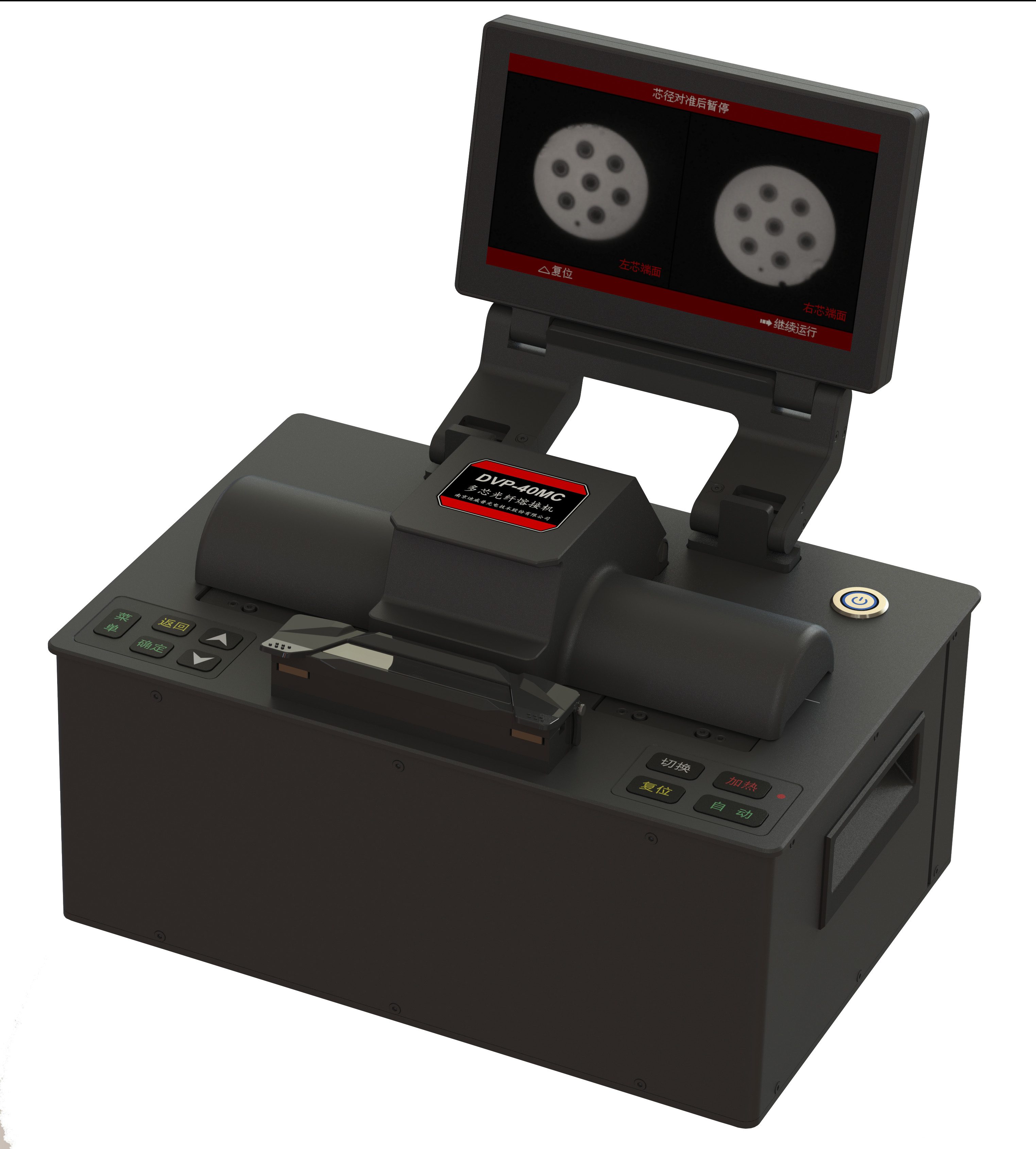
Every fraction of a millimeter lost to misalignment quietly eats away at what a system can actually carry or process. When components sit even slightly off-axis, the contact patch shrinks, stress concentrates in areas never designed for it, and the rated capacity becomes a number that only works on paper. Precision here is not about chasing perfection for its own sake; it is about protecting the headroom that keeps a structure or machine from collapsing under its own intended load.
The same principle shows up in systems that handle flow, data, or motion. A guide rail a few microns out of parallel forces bearings to fight each other instead of sharing the load. That hidden friction lowers throughput long before a failure is obvious. Restoring alignment often unlocks capacity that was never added by upgrading parts, but was always there, buried under small geometric errors.
What makes alignment so unforgiving is that its influence multiplies. Initial error becomes vibration, vibration becomes wear, and wear widens the gap further. Catching those early deviations demands measurement habits that are boring by design, yet they separate installations that hit their rated numbers from ones that limp along at a fraction of what they should deliver.
Overcoming Cladding Diameter Variability in the Field
Cladding diameter drift rarely announces itself. A drum that measures 125.0 µm in the warehouse can show 124.4 µm three floors up after temperature swings and a rough pull through conduit. The first sign is often a cleaver that leaves a lip or a splicer that rejects the fiber as out of tolerance. Rather than trusting the label, field crews should check a short scrap with a digital micrometer or a handheld geometry gauge before terminating. That five-minute step exposes whether the issue is the fiber, the cleaver blade, or the tooling insert.
Once the actual diameter is known, the fix is rarely a setting buried in a menu. Most core-alignment splicers handle minor diameter shifts without help, but V-groove or fixed-clamp units need shims or alternate inserts. For mechanical connectors, swapping to a slightly larger or smaller collet can restore grip. Some technicians keep a small kit of thickness gauges and pre-cut shim stock to nudge a cleaver's clamp into the right range. The goal is not to hit 125.0 µm exactly; it's to keep the fiber from moving during the cleave or splice.
If the variability is consistent across a reel, sorting and labeling by measured diameter pays off later. A bundle tagged '124.6–124.9 µm' can be paired with matching connectors and splice programs, instead of forcing every fiber through the same default setup. When the spread is wider, a mid-span buffer strip and a few test splices usually reveal whether the problem is isolated to one end or the whole length. Field records of diameter drift also help distinguish a one-off bad batch from a chronic supplier issue, which saves more time than any single splice tweak.
Low-Loss Fusion for Dense Spatial Channels
Fusing information across dense spatial channels often introduces unwanted attenuation because each channel competes for the same representational budget. A low-loss fusion strategy addresses this by aligning feature maps in a shared latent space before combining them, using lightweight gating to suppress redundant activations rather than discarding entire channels. The result preserves fine-grained spatial detail that would otherwise be lost during aggressive downsampling or naive concatenation.
One practical implementation relies on learnable per-channel scaling factors that adapt to the input distribution, coupled with a reconstruction constraint that penalizes deviation from the original channel statistics. This keeps the fused representation compact without forcing all streams through a common bottleneck too early. In dense prediction tasks such as semantic segmentation or depth estimation, the approach reduces boundary blur and improves recovery of thin structures, where conventional fusion tends to smear or drop weak signals.
Compared to simple averaging or fixed-weight summation, low-loss fusion maintains a near-constant information flow across layers, which stabilizes training and allows deeper architectures to benefit from multimodal or multi-scale inputs. The overhead is small, yet the gains in accuracy and robustness are consistent, making it a practical drop-in replacement for existing feature merge modules.
Portable Splicing Tools Built for Harsh Environments
In remote pipeline spreads or offshore platforms, a splicing tool that can't handle dust, salt spray, or sudden temperature swings becomes a liability. These portable units are built with sealed electronics and reinforced housings, so technicians can carry them into a trench or up a tower without worrying about contamination or impact damage.
The real difference comes from details like field-replaceable dies, tool-free battery swaps, and pressure sensors that keep crimp force consistent even when the operator is working in gloves. Instead of fragile displays or exposed fasteners, you find oversized controls and weather-sealed ports that shrug off mud, ice, and direct sun.
Maintenance is equally practical: wear parts can be accessed without a full teardown, and the hydraulic system is pre-filled to avoid messy refills in the field. That means less time nursing the tool and more time completing splices on conductors, guy strands, or ground rods where failure simply isn't an option.
Scaling Network Throughput Without Replacing Existing Ducts
The usual assumption is that boosting a network's capacity means tearing up streets and laying new conduits, but that's rarely necessary. In many cases, the existing duct network still has spare cross-sectional area that can be used more efficiently. Pulling a higher-fiber-count cable, installing microducts to subdivide the space, or using air-blown fiber can dramatically increase the number of strands without any civil works. For older routes, removing abandoned cables and clearing debris often frees enough room for a substantial capacity upgrade, and this approach keeps disruption to a minimum.
Even after the physical fiber count is increased, further gains come from the electronics at either end. Coherent optical transceivers and advanced modulation schemes can squeeze far more bits per wavelength than earlier generation equipment, while dense wavelength-division multiplexing multiplies that capacity by running dozens of independent channels over the same fiber pair. Upgrading line cards or adding modular shelves is typically done inside existing equipment rooms, so the duct infrastructure remains untouched. Because the duct is often the most expensive and time-consuming part of a build, keeping it in place while modernizing both the cable and the active hardware delivers most of the benefit of a greenfield route at a fraction of the cost and lead time.
FAQ
It aligns and fuses multiple cores in a single operation rather than handling one fiber at a time. That cuts splicing time significantly while keeping insertion loss low across all cores, which is the main bottleneck in dense multi-core cable deployments.
By bundling several cores into one glass strand, a single cable can carry parallel data channels. The splicer's ability to join those cores without damaging neighboring ones means operators can scale capacity without laying more fiber ducts.
High-density data centers, 5G fronthaul links, and submarine cable landing stations see the biggest gains. They all need compact cabling and fast splicing in tight spaces, and multi-core fiber reduces both physical footprint and labor time.
Core alignment was notoriously tricky because cores sit only tens of microns apart. Older systems often produced uneven loss or weak points. This new type appears to use improved imaging and rotation control to keep all cores aligned during the arc discharge.
It automates most of the alignment and loss estimation, so experienced single-core splicer operators can adapt after a short hands-on session. The main learning curve is handling the larger fiber cladding and verifying all cores after the splice.
Consistent core-to-core alignment reduces stress points and splice loss variation, which helps prevent signal degradation over years of thermal cycling. That reliability is crucial for buried or submarine routes where repairs are expensive.
In many cases, yes. Multi-core fiber can be installed alongside legacy single-core cables, and the splicer allows incremental migration. Operators can light up additional cores later as traffic grows, avoiding a full rip-and-replace.
They need to check compatibility with their current fiber inventory and cleavers. Also, multi-core fiber has a larger coating diameter, so splice trays and closures may need minor adjustments. But the time savings at scale usually offset those initial tweaks.
Conclusion
Multi-core fibers pack several light-carrying cores into a single strand, but splicing them with conventional single-core equipment often leads to misalignment, high loss, and unpredictable channel behavior. The new type of fusion splicer targets these pain points by rethinking the entire alignment process. Instead of relying on surface geometry alone, it maps the actual positions of every core in real time, correcting for rotational offset and core-to-core spacing. This precision matters because even a fraction of a micron shift can throttle capacity or introduce crosstalk between dense spatial channels. Field crews also face cladding diameter swings from batch to batch; the splicer’s adaptive clamping and calibration routines normalize these variations, so a splice made on a Tuesday morning performs the same as one made on a Friday afternoon in a different site.
Beyond the lab, the real test is on the pole or in a vault. The splicer’s low-loss fusion cycle is tuned for the tight geometry of multi-core layouts, keeping attenuation budgets intact across all cores simultaneously. Its portable build shrugs off dust, humidity, and temperature swings, letting technicians work without a cleanroom tent. The payoff shows up in network planning: operators can multiply fiber capacity inside the same duct space that already exists, avoiding costly civil works. By making multi-core splicing as routine as single-core work, this tool clears a path for dense spatial multiplexing outside research showcases—bringing a practical jump in throughput to live networks without waiting for new infrastructure.
Contact Us
Contact Person: Mr XU
Email: [email protected]
Tel/WhatsApp: 86-25-85582828
Website: https://www.dvp.cn/en/