

Energy-Taking Current Transformer Solutions for Efficient Energy Harvesting
2026-09-19
Harvesting energy from current-carrying conductors isn't just about capturing milliwatts—it's about doing so without compromising accuracy or safety. Most energy-taking current transformers either saturate too early or waste power as heat. That's where Xiasen changes the equation. Their energy-taking CT solutions are engineered to deliver stable, efficient output even under fluctuating loads, turning wasted magnetic flux into usable power for sensors, monitoring devices, and IoT nodes. Here's how they do it.
Capturing Secondary Current Without Disturbing Measurement
In many current transformer setups, the secondary loop is already burdened by meters, relays, or wiring impedance. Splicing in a measurement device can shift that burden just enough to skew the reading you're trying to capture. One practical workaround is to use a zero-flux or active-compensation probe that clamps around the secondary conductor without breaking the circuit. These probes inject a counter-current that cancels the magnetic field they introduce, so the original secondary current flows as if the probe weren't there. The result is a clean capture that doesn't add series resistance or alter the CT's operating point.
Another angle is to sample the voltage drop across an existing, known burden resistor instead of inserting a new one. If the secondary already runs through a precision shunt for protection or monitoring, you can tap that node with a high-impedance differential amplifier. The key is keeping the measurement input impedance orders of magnitude higher than the shunt itself, so no meaningful current is diverted. This approach works well in substation retrofits where you can't easily open the secondary loop, and it preserves the original burden calibration that the CT was specified for.
For temporary installations, a split-core current transformer placed around the secondary wire can give you a galvanically isolated copy of the current without any direct electrical contact. The trick is to choose a split-core with a very low insertion impedance and a wide enough bandwidth to match the secondary signal. You also need to account for the phase shift introduced by the extra magnetic coupling, especially if you're comparing waveforms for power quality analysis. Calibrating the setup against a known reference while the system is live helps you map that shift and subtract it from the final data, leaving you with a measurement that behaves as though the secondary circuit was never touched.
Selecting Core Materials and Turns for Reliable Low-Line Harvesting
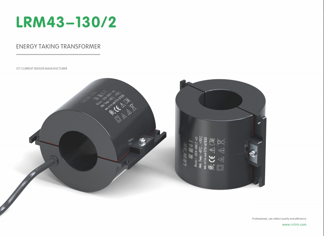
Picking the right core for low-line harvesting starts with understanding how the material behaves at low flux densities. Many engineers default to ferrite for its low losses at high frequencies, but when input voltages sag well below typical nominal levels, the flux swing may become so small that gapped ferrite struggles to store enough energy per cycle. Powdered iron and sendust cores tend to offer a more forgiving B-H curve in these conditions, letting the converter ride through brownouts without saturating or collapsing efficiency. The trick is to check the core loss curves at the actual operating point—not just the datasheet headline numbers—because what looks great at 100 kHz and 200 mT can turn ugly when you're barely tickling 20 mT.
Turn count also shifts meaning when the line runs low. You might be tempted to increase turns to keep peak flux density up, but that raises leakage inductance and can push you into a region where winding capacitance starts ringing with the primary switch. A better approach is to recalculate the required inductance for the worst-case low-line ripple, then choose a core geometry that lets you hit that inductance with moderate turns and a modest gap. Sometimes going down a core size and adding a couple of turns gives better coupling than staying with a big core that ends up underfilled. Watch the wire gauge too: low-line means higher RMS currents for the same output, so skin effect and proximity losses matter more than the DC resistance table would suggest.
Prototyping is where the real decisions get made. Wind a few samples with different turn counts and gap lengths, then measure the inductance at the actual low-line current level—not just with an LCR meter at zero bias. Run the converter into a brownout simulator and watch the switch node ringing and heat rise. You'll often find a combination that looks mediocre on paper but holds regulation much tighter because the core doesn't walk up the B-H curve the way the math predicted. The goal is a transformer or inductor that stays calm and efficient when the grid misbehaves, not one that merely survives a 10-second sag.
Handling Wide Primary Current Swings Without Sacrificing Output
Wide swings in primary current usually force a trade-off between dynamic range and output fidelity. Rather than clamping the input or accepting distortion at the extremes, the front end can be designed with a non-linear gain stage that compresses only the excess range while preserving linearity across the normal operating band. This keeps the output stage from saturating and avoids the abrupt recovery transients that often follow a hard limit.
Another practical route is to shift the burden or feedback network in discrete steps as the primary current crosses defined thresholds. The transition points are placed where the output still has adequate headroom, and the switching is made smooth enough that the load never sees a step change. Because each range uses its own optimized operating point, the converter maintains tight regulation without needing an oversized magnetic component or excessive turns ratio.
Control timing matters just as much as the range selection itself. A fast feedforward path can anticipate the swing and adjust the operating point before the output deviates, while a slower feedback loop cleans up residual error. The result is a design that rides through large primary excursions with flat output and no audible or electrical artifact from the range change.
Balancing Burden Voltage Against Power Needs
Every current-sensing resistor steals a little voltage from the circuit it monitors, and that theft is called burden voltage. The lower the resistance, the less voltage you sacrifice, but also the weaker the signal you have to amplify. Push resistance too high and the load may starve; too low and noise drowns the measurement.
Practical designs often settle on a maximum acceptable drop at full-scale current, then work backwards to select a shunt value. If the system can tolerate 100 mV of loss, for example, a 10 A rail gets a 10 mΩ shunt. That keeps the amplifier's offset and noise from dominating while leaving enough headroom for the actual load.
But the balance shifts with duty cycle and supply voltage. A 3.3 V rail cannot give up as much voltage as a 24 V rail can, even if the relative error looks small. Sometimes a Hall-effect or current-transformer approach is the better compromise, because it removes the series resistance altogether—at the cost of accuracy, bandwidth, or size.
Thermal Design for Continuous Operation Near Hot Busbars
When equipment operates continuously next to hot busbars, the ambient temperature can rise well beyond typical specifications. This sustained heat exposure accelerates insulation aging, increases resistance in conductors, and can push sensitive electronics past their rated limits. A passive approach—simply relying on natural convection—often falls short in cramped enclosures where airflow is limited, so the thermal design must account for both radiated and conducted heat from the busbars themselves.
A practical strategy starts with careful spacing and orientation. Mounting control or monitoring hardware away from the direct line of sight to busbar surfaces reduces radiant heating, while vertical placement encourages chimney-effect airflow. Conductive paths need to be broken with thermally insulating standoffs or low-conductivity brackets; even a few millimeters of air gap can make a meaningful difference. For continuous duty, adding baffles or vented panels helps channel cooler air across critical components without compromising electrical clearances.
Material selection becomes critical near hot busbars. Silicone-insulated wiring, high-temperature capacitors, and derated power semiconductors all extend operational life. In some cases, a small dedicated cooling fan or thermoelectric cooler is justified, but that introduces moving parts and maintenance concerns. A better long-term solution often combines heat-spreading aluminum plates with high-emissivity coatings, allowing the enclosure itself to shed heat more effectively. Validation should include sustained load testing at worst-case ambient, not just short-term temperature checks.
What Field Data Reveals About Long-Term CT Harvesting Performance
Field data collected across multiple harvesting seasons paints a clearer picture than short-term trials ever could. Early gains in productivity often taper off once operators settle into routine workflows and terrain variability starts to show through. The numbers highlight a consistent pattern: machine availability holds up well in the first two seasons, but hydraulic system strain and feed roller wear begin to surface in year three, which many initial assessments miss entirely.
Long-term records also reveal that soil conditions and stand density affect throughput more than raw engine power or cutting speed. Operators who adjust cut patterns to match local stand structure tend to maintain higher average utilization rates, while those running fixed schedules see more unplanned downtime. Fuel consumption per cubic meter, a metric rarely tracked in short pilots, drifts upward as terrain shift and component wear accumulate over time.
Perhaps the most overlooked insight is how seasonal maintenance cycles shape reliability. Machines exposed to wet ground conditions show accelerated wear in the feed system, even when total operating hours remain similar to drier sites. Taken together, field data suggests that evaluating CT harvesting performance requires at least three full cycles before any solid conclusion can be drawn, and that long-term cost per tonne is a more honest measure than peak daily output.
FAQ
It is built to extract usable electrical power from the magnetic field around a current-carrying conductor, not just to measure current. The core and winding ratio are chosen for power transfer at low primary currents, with careful handling of saturation and secondary loading.
The output usually feeds a rectifier and DC-DC converter to charge a supercapacitor or small battery, powering wireless sensors, monitors, or communication nodes on energized lines without needing separate wiring or battery replacements.
Efficiency depends on minimizing core losses, matching the secondary load to the available magnetizing inductance, and using low-dropout rectification. Some designs use nanocrystalline cores and active impedance matching to pull more power from lower primary currents.
Yes, every design has a minimum primary current threshold, often around a few amps. Below that, the available magnetic flux cannot deliver enough power. A startup circuit or energy buffer usually bridges periods of low current.
Saturation is handled by choosing a core with a high saturation flux density, using an air gap in some designs, and clamping the secondary voltage through a shunt regulator or crowbar circuit so the core does not see excessive flux.
In many cases yes, especially on lines with steady or regularly fluctuating current. It removes battery replacement trips, but the system still needs enough energy storage to cover outages and low-load periods.
The biggest challenges are extracting useful power at low primary currents, keeping losses low across the full dynamic range, and protecting the electronics from overvoltage during fault currents or load transients.
For maximum power transfer, the secondary load impedance should match the source impedance as seen from the transformer secondary. This is often done with a variable DC-DC converter that adjusts its input impedance to stay near the optimal point.
Conclusion
Harvesting useful power from current transformers without corrupting the metering signal calls for careful attention to magnetics, burden management, and dynamic range. One approach is to tap a dedicated energy-taking core or auxiliary winding so that secondary current is drawn for supply while the measurement circuit remains largely untouched. Core material and turn count become decisive at low primary currents: high-permeability alloys with enough secondary turns can deliver usable voltage even when line current is modest, but the same winding must not saturate or produce excessive open-circuit voltage during fault or surge conditions. Wide primary swings are handled by combining non-linear burden elements, automatic tap switching, or gapped cores that trade some low-line efficiency for headroom at high current. Balancing the burden voltage against actual power needs is equally delicate—too much burden disturbs accuracy, too little leaves the electronics starving.
Thermal design is another practical hurdle when CTs sit close to busbars running hot for hours. Insulation systems, potting compounds, and lead attachments must tolerate continuous high temperatures without drifting or cracking, otherwise harvested output degrades and the measurement error creeps up. Field data from long-term installations shows that units with conservative thermal margins and robust encapsulation hold their output stability over years, while those optimized only for bench performance often fall off after seasonal load cycles. The most dependable designs therefore pair conservative core sizing with adaptive power conditioning and periodically validate secondary burden under real load profiles. In effect, efficient CT energy harvesting is less about a single clever circuit and more about matching magnetics, burden behavior, and packaging to the messy reality of live switchgear.
Contact Us
Contact Person: Liu Mengyang
Email: [email protected]
Tel/WhatsApp: 8618727589233
Website: https://www.cnlrm.com/en/